Elektra Bregenz GIF 3003 X dishwasher repair

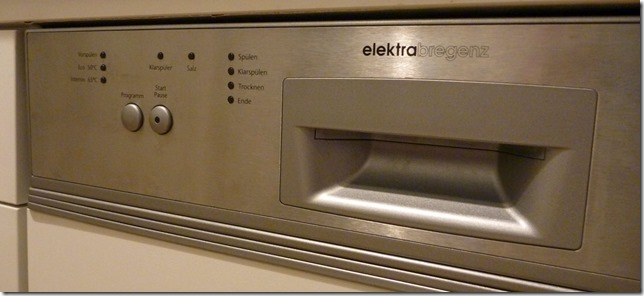
dishwasher-front

A few weeks ago I had trouble with my dishwasher (Model: Elektra Bregenz GIF 3003 X). The problem was, that the dishwasher suddenly switched itself off during the washing program.

It seemed as if the dishwasher was stuck in the following loop:

  1. the dishwasher turned off (all lights go out; as if you have switched it off)
  2. For about a second the dishwasher stats off
  3. The dishwasher turns on again (lights go on)
  4. The dishwasher starts washing and instantly turns off again (so back to 1)

I discovered that the problem doesn’t occur if I select the “precleaning” program (the short program where the dishes are only washed with cold water). This was a point to start the investigation. I took the front panel apart to get to the electronics inside and do some measurements.

open-front control-board

To remove the front, open the dishwasher and undo the screws that are on the inside of the front door. The two screws in the middle hold the wood faceplate. You don’t need to take the faceplate off, but It makes the handling a bit easier (however to mount it back on it is good to have someone that helps you).

When you have removed all the screws, the front will split into two parts. The electronic is positioned at the front left corner (where the buttons are). It is enclosed in a separate plastic case that you can flip open after you remove the cables.

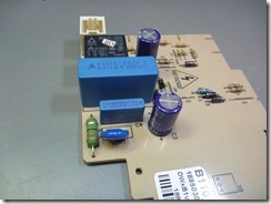
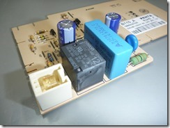
When you look on the second picture you may already can spot that there are some burning marks on the backside of the plastic cover right where the relay sits.

When I inspected the PCB closer, I saw that the relay, that switches the heating element, had a hole in it. Yes, a hole!

relay relay-hole

I have no idea what can cause a relay to look like this. I measured the heating element and the resistance was fine. So I went ahead and replaced the relay … but that didn’t solve the initial problem. The dishwasher still switched itself off.

After some further measurements I found that the real cause of the problem was the power supply. This dishwasher uses a capacitive power supply (Wikipedia: https://en.wikipedia.org/wiki/Capacitive_power_supply). With the LCR meter it was quite easy to find that the 1µF capacitor had died. I think this is a little design flaw. Because of the placement of the control circuit, the capacitor is exposed to the inside temperature of the dishwasher (~ 65°C when the dishwasher is working). There is hardly any thermal insulation present. Fore sure this has reduced the lifetime of the capacitor significantly.

caps replaced components

So the only thing to do was to replace the bad capacitor and everything was working again perfectly.

For all of you that don’t want to repair the control board yourself: You can also buy the whole board as a spare part and replace it (no soldering needed). The following search terms may help you in finding the correct replacement:
Product code: 7604683742 / Replacement part code: 1885030105


Marantz PM7200 repair

Marantz PM7200

During the last RepairCafe I got a Marantz PM7200 amplifier in my hands that had a very interesting fault.

Whenever the output signal reached a certain level, the amplifier switched the outputs off (as I learned later on, that is called the protection mode). This symptom could be provoked by either increasing the input level or increasing the amplification by turning the volume control. The effect occurred on the left and right channel. It didn’t matter if I put a signal at both or only at one channel. Also the source of the signal didn’t matter.

For “on the road” signal generation I use the android app called “Function Generator” (https://play.google.com/store/apps/details?id=com.keuwl.functiongenerator&hl=de).

My first guess was that the output stage must have a problem (shorted output transistor or something similar). However I measured no significant DC offset and all the signals seem to be just fine. My second guess was a thermal issue but that also led me to nothing significant. I also measured the power supply and all the other “most likely suspects” … nothing turned up. So sadly I wasn’t able to repair the amplifier at the RepairCafe and decided to take it with me to investigate further.

At home I did some more testing. The problem was also independent of the Mode (Class AB or Class A) and also seemed to be invariant of the frequency (I tested from 50 Hz to approximately 10 kHz). Another strange effect was that the error was instantly resettable. When the amplifier switched the outputs off you just had to reduce the volume a bit and it instantly turned back on again. The fast reaction seemed to make a thermal issue very unlikely.

Main Schematic-test points

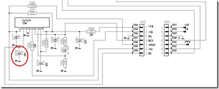
If you search on the internet, you can find a service manual which is really helpful because it has all the schematics in it. Because all the signals I measured so far seemed fine, I decided to investigate the protection circuit and measure the signals there. By studying the schematic of the main amplifier one can see, that at the end of the output stages the signal gets tapped of to the protection circuit (marked with the red box). This signal is for DC offset detection.

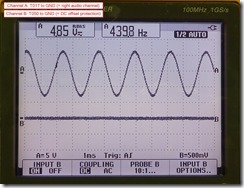
I fed a sine wave (440 Hz, 500 mVpp) to the right and left channel (0° phase shift). I increased the volume so that the error just show up. When I measured the signal (T050 to GND) I saw the same signal shape as at the output stage (T017 to GND). The measurement is shown at the screenshot below. The test points are marked green in the schematic above.

Measurement1

The protection circuit has a TA7317P IC in it. If you look at the datasheet you see that the IC will send the amplifier to protection mode when a voltage level of approximately 1 V is exceeded. With this information it seems plausible that (given the signal at T050 as shown above) the amplifier switches to protection mode.

My next test was to fed in the same signal as before (440 Hz, 500mVpp) but this time I shifted the phase of the left channel by 180°. My thought was, that with the phase shifted input signal, there should be no signal at T050 (left and right signal cancel each other out). With the so fed signal the amplifier didn’t show the error anymore! This led me to the conclusion that the amplifier is probably working fine and just the protection circuit has a defect.

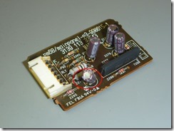
Protection Circuit  Protection Circuit-PCB

Some further investigation showed, that there is a capacitor (2278) attached to the DC offset line that should flatten all the AC signals. When I measured the capacitor with the LCR-Meter there was no reading of the capacitance possible (the capacitor was dead). I replaced the capacitor with a new one with the same values (I used a 105 °C rated) and did the first measurement (with 0° phase shift) once more.
Measurement-after-cap-replacement

As to be expected the signal at T050 changed drastically. All the AC part was gone and the amplifier didn’t turn off anymore! Yeah … problem found and fixed!
To be safe I replaced all four electrolytic capacitors (2278, 2281, 2282, 2279) on the protection board. I measured them later on and they all where in pretty bad condition.

Protection Circuit-IR2

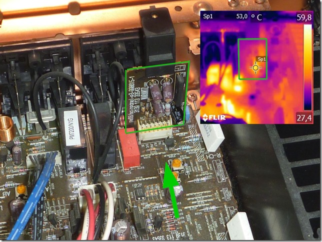
I did some thermal imaging of the protection circuit board. The picture above was taken after 5 minutes idle time of the amplifier (switched on but no signal). The green arrow indicates the approximate direction of the IR Image. The green frame marks the protection circuit board.  As you can see there is a hotspot (53 °C) very close to the broken capacitor caused by two 1 W resistors (3364 and 3358). The permanent exposure to heat probably killed the capacitors.

IR-Overview

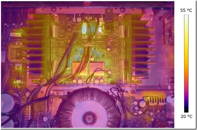
I also did a thermal image of the whole main amplifier board to find other hotspots. To recognize the components better, I made an overlay with a normal picture (I used gimp for that). The overlay is not perfect because of an slightly different angle and focal length of the two cameras. You can see that there are areas that get 55 °C hot if the amplifier is idle (the picture was taken after 10 minutes idle time). In the center area there are some linear regulators that have capacitors close by. I measured some of those capacitors and all seem to have degraded so I went ahead and replaced the ones that where close to heat sources (2264, 2263, 2256, 2255, 2268, 2267).

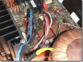
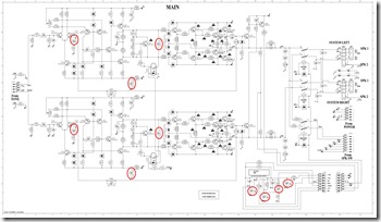
Main PCB - replaced components  Main Schematic-replaced components

In the schematic above I marked all the components that I replaced. If you replace them, be sure to use 105 °C rated capacitors. The capacitors of the power supply where ok so I didn’t replace them. Be sure to do a DC offset voltage alignment and an idling current adjustment after you replace those components. At my unit the values have drifted a bit. You find detailed instructions on how to perform this adjustment in the service manual at page 34.
I tested the amplifier for several hours (at reasonable loud volume) and no error occurred. Fixed Smiley


Fluke 233 Display repair

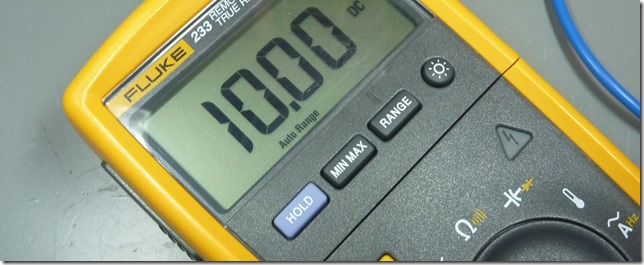
Fluke 233

Recently I scored a broken Fluke 233 on ebay. On the pictures it seems that the meter was in good shape. Only the display seems to be broken.

When the unit arrived I was able to turn it on and the continuity buzzer worked just fine Smiley

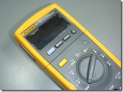
broken display

The special thing about this meter is, that you can separate it into the base unit and the display unit. They communicate by wireless transmission up to 10m.

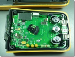
At first let’s have a look at the base unit. I took it apart in order to check if the right fuse is in the meter (you never know on used equipment).

base unit

The build quality is (as to be expected from fluke) superb. This unit seems to be in good condition. No parts were damaged or dirty.

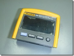
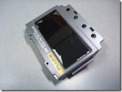
Next I took a closer look at the top unit. As you can see on the pictures the LCD Display was damaged. I ordered the replacement part from the Fluke distributor in Austria (Analog & Digital Messtechnik; http://www.kalibration.at/). The part number for the broken display is “LCD RDX (3385697)”.

You can find part numbers and service instructions in the calibration manual. Just search “fluke 233 calibration manual” with Google and you will find it straight away.

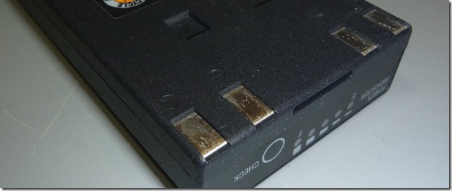
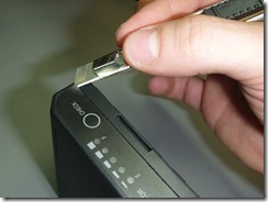
top unit1top unit2battery terminals

On two of the battery terminals there was a bit of corrosion. Probably someone had left batteries to long in there. With a screwdriver and some alcohol prep pads the dirt came off really easy.

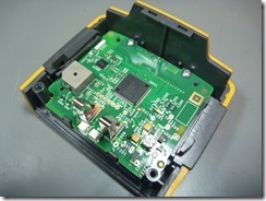
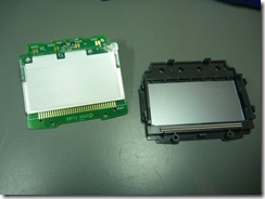
top unit pcbtop unit pcb separatedlcd-assembly

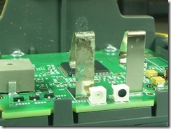
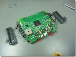
After you removed the PCB from the housing the display is still connected to the PCB. You have to pry open the red marked plastic clips gently. The LCD assembly will then come off.

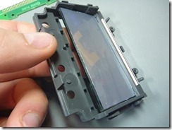
lcd backlighttilt lcdconductive rubber

In order to change the LCD you have to lift it slightly up and slide it out in the directions of the buttons. At my unit the conductive rubber zebra stripe was stuck to the PCB. I used a pick to separate it carefully.

I installed the new LCD and reassembled everything again. The yellow rubber was a bit dirty. Alcohol prep pads work good to clean the rubber and let meter look like new. Smiley


Battery replacement on the Olympus BN-1

Olympus-BN-1

After some years the batteries inside the Olympus high voltage flash pack die. Olympus does not offer replacement Batteries. You have to throw away the whole battery pack and get a new one (which is about 200 €).

I thought that – before throwing it away – I give it a go and try to replace the batteries myself.

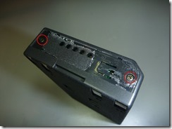
The first thing you have to do is to Carefully peel off the plastic cover. Its easiest to start at a corner. You should warm up the foil a bit (use a hair-dryer or a rework station). When the glue is warm, it comes off rather easy. Don’t make it to hot (or you will be melting the plastic). I used a hot air station with the settings 100°C and 60l/min. Just make the plastic warm (~ 50°C) that is more than enough.

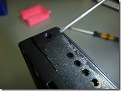
Under the plastic you will find two PH0 screws. After you remove them you can lift out the plastic cover of the small PCB.

remove plastictop-screwsPCB cover

You will see the PCB that is again secured with 2 PH0 screws. After those screws are removed you can lift out the PCB a bit. An the rear side of the PCB there are 5 cables. 3 thicker ones (red, white, black) and two smaller black cables. The two smaller black cables to a temperature sensor. Be careful not to cut or damage them.
Olympus has molded the plastic case together. There is no easy way to get this apart.

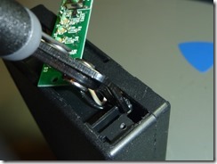
The first step is to cut two small connections that are under the PCB. I used a side cutter to split them. Be careful not to cut the cables.

cut-connections

The next step is the most time consuming.  You have to cut around the case where the upper and the lower part have been welded together. I used a cutting blade and repeatedly cut along the edge.

BE PATIENT! … it took me nearly half an hour to get the case open. Be careful not to cut to deep (the batteries are close behind the wall). You can feel it when you penetrated the case. Just take your time and work slowly and carefully. I used a prying tool to separate the upper and lower part just a bit so that the cutting knife gets a bit more room.

cutting1cutting2

The sides went apart easy … but at the bottom the case had a better connection. I used two prying tools and pushed them right till the bottom. With patience and a little force (tilt the upper part towards the bottom) the case snapped apart.

open-bottom

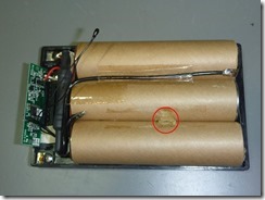
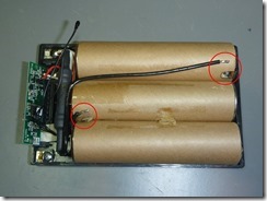
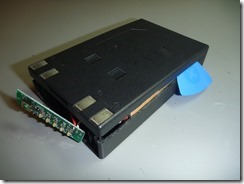
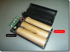
There are 6 single sub C cells that are joined in serial.

battery packbatterypack-dimensions1batterypack-dimensions2

The six batteries are all wired in series (6 x 1,2V = 7,2 V).
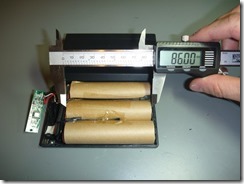
The two batteries in series are 86mm long and have a diameter of 22,5mm.
So our replacement batteries have to be smaller than 42mm x 22,5mm (length x diameter) .

In order to remove the battery pack from the case you have to carefully loosen the temperature sensor from the battery. The sensor is podded in some kind of elastic clue. Just use a screwdriver and carefully peel it out.

After that you can unsolder the wires that connect to to the battery pack.

temperature-sensordesolder contacts

I thought about replacing the cells with eneloop; my tests showed that they provided to less peak current. The charging time for the flash would have been far to long.

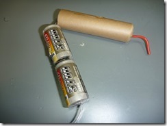
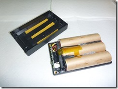
In the electronic shop nearby they had battery packs where the single cell size matched. These packs are designed for RC usage. This means that they can provide a high peak current (perfect for our application). I took cells that had a higher capacity (3700mAh instead of 2600mAh);. Sadly there was no pack with the right alignment of the single cells so I had to align them. I reused the paper cover to isolate the new battery pack.

replacement-batteriesbattery arrangementreuse-cover

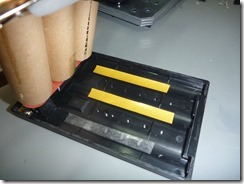
To fixate the new battery pack in the cover I used very thin double side adhesive tape (some Tesa that is usually used for sticking photos to an album).

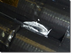
I resoldered the connection wires and glued the temperature sensor in place. Before gluing the temperature sensor I put some thermal compound between the battery pack and the temperature sensor.

fix battery pack1thermal compoundpartly-reassembled

Don’t stick on the top cover of the battery pack right now. There would be a small gap where we cut the case apart.

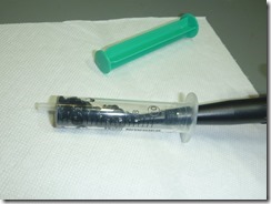
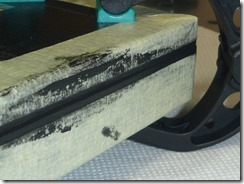
I used construction silicone glue to rejoin the case. In order to be able to allot the silicone more accurate I decanted it from the big cartridge to a smaller syringe. You also should prepare a small bowl with water and add a drop of dishwashing liquid to it. You can then dip your finger in this fluid and the silicone will not stick. This way you can smoothen it later on.

siliconedecantdishwashing liquid

Before applying the silicone you should put tape around the outside of both of the case halves. I positioned the tape approximately 1mm away from the edge.

tape

Apply a small amount of the construction silicone around the edge of the lower case. Don’t use to much or it will get messy once you put the case together. If it really is too little (trust me there wont) you can apply more when the case is put together.

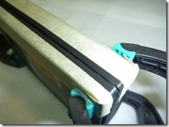
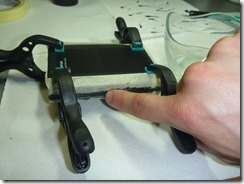
After you applied the silicone you can put the case together. I used four clamps to press it so that there is hardly any gap. Now you can use your finger (dip it in the dishwasher liquid first) to smoothen / remove the silicone that got squeezed out of the case.

apply siliconesmoothenfinished edge

Let it dry for at least 24 hours (depending on the type of silicone you used). After drying you can remove the tape.

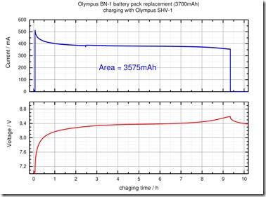
I monitored a full charging cycle with my bench top multimeter. The battery was charged with the Olympus charger (I had small copper strips to tap of the connections). I wanted to ensure that there are no problems (like a timeout) because of the increased capacity.

charging curve

The charging worked just fine and took approximately 10 hours.

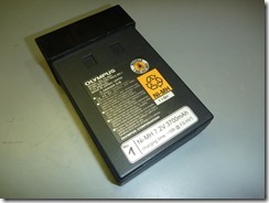
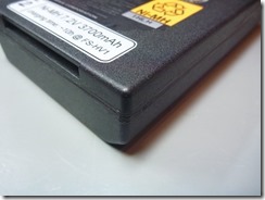
The last thing I did was to put an additional marking on the battery pack so that it can be identified easily.

markingfinal result

All finished Smiley